NDT Services

Sonomatic RAIS offers Non-Destructive Testing (NDT) services to companies across a multitude of industries that possess assets or infrastructure. Our comprehensive range of conventional and advanced NDT services ensures our clients receive first-class deliverables. As RAIS continues to grow and evolve within the modern market, we utilise the latest technologies to ensure we deliver the best results to our clients whilst ultimately saving time and money.

With over 40 years of experience in the inspection industry, Sonomatic RAIS provides highly trained PCN-qualified technicians to perform a number of advanced non-destructive testing (NDT) techniques that work to ensure reliable operating processes within regulations, codes, and to our various accreditations.

In need of an NDT inspection for your project? Get in touch with us today to learn more!

Conventional NDT Services

Safety, reliability, environmental requirements and regulations all mean that companies across multiple sectors have a responsibility to maintain the integrity of their equipment.

Sonomatic RAIS has a proven track record in delivering a wide array of conventional non-destructive inspection and non-destructive testing methods. Sonomatic RAIS provides NDT by planning campaigns, advising clients on NDT methods, and providing

recommendations and solutions to ensure code compliance with both international and British standards.

Underpinned by specialist access and robotics, RAIS provides a base inspection service and manages the end-to-end solution from high mobility specialist access using rope access, engineered decking and netting systems through to deployment via ROV, UAV, or crawler deployed systems.

Our Conventional NDT Services Include but are not limited to:
  • Ultrasonic Testing (UT)
  • Magnetic Particle Testing & Inspection (MT)
  • Radiography: on-site, mobile dark-room, digital and on ropes
  • Pre-heat and post weld heat treatment
  • Hydro-Testing
  • Visual Inspection
  • Eddy Current (EC)
  • Liquid Penetrant Inspection (DPI)
  • Positive Material Identification (PMI)
  • Ferrite Testing
  • Vax Box Testing
  • Hardness Testing
  • Coating Thickness Measurements (including cladding)
  • Tank Floor Scanning - Floormap X

Advanced NDT Services

Sonomatic RAIS has proven experience in a range of highly specialised advanced NDT inspection services. Our NDT technicians are highly trained along with years of experience, and our NDT testing methods have been developed over years of experience.

Sonomatic, is a leading provider of advanced NDT inspection services to clients in various industries. Sonomatic brought innovation to the market by introducing Time of Flight

Diffraction (TOFD) in the 1980s and bringing world-leading technology to our clients.

The team is unique among inspection service providers in that they develop their inspection systems and scanners to meet specific requirements for inspection performance, deployment and in-field reliability.

OUR SPECIALISED NDT SERVICES INCLUDE but are not limited to:
  • Pulsed Eddy Current (PEC)
  • TOFD (Time of Flight Diffraction)
  • ACFM
  • Pipe Elbow Inspection
  • Surface Array & Tube Inspection
  • Heat Exchanger Tube Bundle Inspection
  • Phased Array
  • Long-Range UT
  • Short Range Guided Wave
  • Composite Wrap Application & Inspection
  • Tank Floor Scanning
  • Flux Leakage
  • RMS Crawler
  • EMAT
  • 3D Laser Scanner
  • Remote Digital Visual & Robotic

NDT Services of Wind Turbines

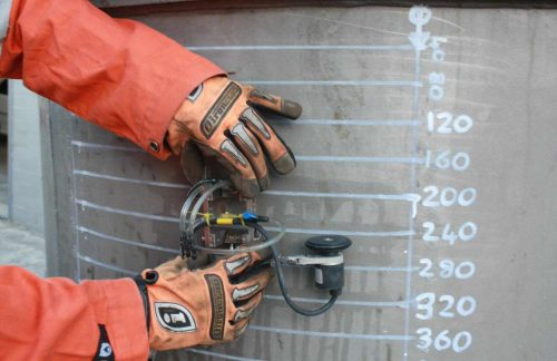
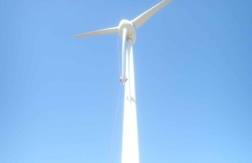
Wind turbines inevitably encounter wear and tear, damage and require proactive maintenance and inspection throughout their lifecycle. Non-Destructive Testing (NDT) can be especially effective at identifying issues or defects on the main rotor shaft, circumferential weld flanges and ancillary bolts.

Sonomatic RAIS and Vertech Group in the ASIA Pacific, provide TOFD, ACFM and Phased Array Bolt inspections for wind turbines and their component parts during multiple stages of their lifecycle, ensuring the best performance and minimal costs for the operator. Some of the benefits of Advanced NDT inspection include:

  • Fast screening techniques
  • Early detection of fatigue cracks
  • Fully recordable data for archiving
  • Data comparison for repeat inspections
  • Reliable testing methods

NDT Techniques

Alternating current field measurement (ACFM) is an electromagnetic technique used for the detection and sizing of surface breaking cracks in metallic components and welds. It combines the advantages of the alternating current potential drop (ACPD) technique and Eddy Current Testing (ECT) in terms of defect sizing without calibration and ability to work without electrical contact respectively.

The Alternating Current Field Measurement – or ACFM – technique was specifically developed to detect and size surface-breaking defects on and around rough welds through several millimetres of non-conductive coating. This is a key advantage because just the costs associated with paint removal, post-MPI re-blasting, and recoating are typically four or five times more expensive than the MPI itself.

While the main failure point in storage tanks is corrosion in the floor plates, from either the top surface or from the underside, the welded sections are also a direct source of damage mechanisms. ACFM is proving itself as the most cost-efficient and trusted method for inspecting storage tank welds to supplement corrosion mapping, successfully detecting large cracks often missed by MPI.

You can’t deny the cost savings of ACFM over MPI; overall, ACFM jobs are typically six times less expensive than their MPI counterparts while providing the added value of a more reliable inspection with data-rich information to pass along to the asset owner.

Benefits:

  • Applicable for base material or welds, ferritic or non-ferritic conductive metals
  • Can be used on hot surfaces, underwater, or in irradiated environments
  • Provides both depth and length information
  • Accurate sizing of defects up to 25mm in depth
  • Requires minimal surface preparation and can be applied over paint and other coatings
  • Applicable for under water inspection as well as normal inspection
  • Inspection data can be stored and analysed offline
  • Inspection can be encoded
  • Provides a permanent record of indications
  • Ongoing monitoring capability
  • High temperature capability

Applications:

  • Applicable for base material or welds, ferritic or non-ferritic conductive metals
  • Can be used on hot surfaces, underwater, or in irradiated environments
  • Provides both depth and length information
  • Accurate sizing of defects up to 25mm in depth
  • Requires minimal surface preparation and can be applied over paint and other coatings
  • Applicable for under water inspection as well as normal inspection
  • Inspection data can be stored and analysed offline
  • Inspection can be encoded
  • Provides a permanent record of indications
  • Ongoing monitoring capability
  • High temperature capability

Eddy Current Testing (ECT) is used to measure the intensity of electrical currents in a magnetic field. Eddy current testing utilises AC current in a coil near or around a specimen, inducing circulating eddy currents in the material's surface. Flaws and material differences affect these currents, altering the coil's current via mutual induction. Flaw detection relies on measuring electrical changes in the coil, often focusing on voltage changes. Key factors influencing eddy currents include specimen conductivity, magnetic permeability (for ferromagnetic materials), coil-specimen distance, AC frequency, and dimensions. Calibration on test specimens is common, and eddy current testing is highly sensitive to flaws. Equipment ranges from basic meters to advanced computer-programmed systems, with applications including crack detection, component sorting, and metal quality control.

Eddy current inspection is often used to detect corrosionerosion, cracking and other defects in tubing using electromagnetic induction. A probe is inserted into the tube and pushed through the entire length of the tube. Eddy currents are generated by the electromagnetic coils in the probe and monitored simultaneously by measuring probe electrical impedance.

3D inspection utilises the latest developments in the market offering high definition surface mapping using a combination of visible light or low laser. It can act as a depth pit gauge adding a benefit of repeatability to the inspection. By using 3D inspection we can map large complex shapes with reduced time on site.

Sonomatic RAIS offers Pulsed Eddy Current (PEC) using Eddyfi® Lyft™ inspection technology. The system allows measurements to be taken through any non-conductive materials such as insulation, protective coatings, concrete, and marine growth, without requiring any direct contact with the inspection surface. State-of-the-art instrument; real-time C-scan imaging; fast data acquisition (up to 15 readings per second) with grid and dynamic scanning modes; and great flexibility thanks to extension cables, probe shoes, and an extension pole. Using the Lyft probes, Sonomatic can scan through thick metal and insulation.

Post Weld Heat Treatment is an essential part of both the operation and maintenance of assets in the fabrication, oil & gas and power industry. The welding process can unintentionally weaken equipment by imparting residual stresses into a material which can lead to reduced material properties. This said, Post Weld Heat Treatment (PWHT) is a method used for reducing and redistributing said residual stresses in materials ensuring that the material strength is retained after the welding course. It is also used as a method of hardness control or even to enhance material strength.

In some standards PWHT is compulsory for certain grades or thicknesses, otherwise it is dependent on the material type and the service requirements. Other factors that impact the need for this Inspection are the welding parameters, the likely mechanism failure, its alloying system, or whether it’s been subject to Heat Treatment previously. Generally, the higher the carbon content and/or the higher the alloy content in materials, the more likely it is to need PWHT after welding activities.

If PWHT is neglected, residual stresses can combine with load stresses to exceed materials limitations which can lead to weld failures, and weld cracks and make a weld vulnerable to brittle facture.

At Sonomatic’s NDT Facilities, we have large specified areas for Heat Treatment activities which hold permanent Heat Treatment machines and have the allocated floor space to accommodate all sizes of pipework. In addition, utilising portable equipment, we can offer PWHT at our client's sites at both onshore and offshore locations. At our NDT facilities, we also provide the Non-Destructive Testing required for both Pre and Post PWHT, including magnetic particle inspections and radiographic inspections.

Ultrasonic Testing is a non-destructive testing method used for obtaining wall thickness measurements to determine any erosion and/or corrosion damage and for identifying flaws including weld root erosion and fatigue cracking in welded components.  UT Inspection works for determining both internal and external defects and is an accurate measuring tool for establishing the exact location and depth of noted flaws.

These are normally applied to structures that are more often subject to corrosion, erosion, and internal defects such as laminations or inclusions.

They are also applied to welds to detect fabrication defects and when in-service to detect weld root erosion and fatigue cracks. These techniques rely on favourable orientation of the imperfections to be noted relative to the direction of the applied ultrasound. The geometry of the imperfection such as pitting is also a main consideration.

Sonomatic technicians are qualified for the full range of UT testing techniques from:

  • Thickness Checking (UT 3.0).
  • Ultrasonic Testing of Welds (UT 3.1 3.2).
  • T-Pieces (UT 3.7).
  • Nozzles and Nodes (UT 3.8 3.9).
  • Forgings and Castings.

Electro Magnetic Acoustic Transducer (EMAT) is an Ultrasonic Testing (UT) technique that generates the sound in the part inspected instead of the transducer. An EMAT comprises a magnet and an electrical coil. When a current is passed through the coil, eddy currents are induced in the component under test. The static magnetic field exerts a force on the eddy currents. If the current passing through the coil is an alternating current, then both the eddy currents and the force will change direction with the change in the current. The oscillating force causes the particles of the component to oscillate, generating an acoustic wave which then propagates through the component. For the EMAT to work, the component needs to be of electrically conducting material.

Hydro testing of pipes, pipelines and vessels is performed within our specially designed and constructed Hydro Bays, to expose defective materials that may have missed prior detection, to ensure that any remaining defects are insignificant enough to allow operation at design pressures, to expose possible leaks and to serve as a final validation of the integrity of the constructed system. ASME B31.3 requires this testing to ensure tightness and strength.

Buried high pressure oil and gas pipelines are tested for strength by pressurising them to at least 125% of their maximum allowable operating pressure (MAOP) at any point along their length.

Hydrostatic tests are conducted under the constraints of either the industry’s or the customer’s specifications or may be required by law.

Applications:

Pipeline Testing

As mentioned above, hydrostatic pressure testing within pipes and pipeline systems is crucial to many operations and projects.

Such tests ensure that – by using a specified test pressure – a pipe system is able to withstand the pressure from the other procedures being performed in the project. This provides peace of mind when it comes to the structural integrity and overall safety of various pipeline projects.

Pressure Vessel Testing

Just like with pipes, pressure vessels need to undergo a hydrostatic test to ensure they can hold their durability under various pressure levels.

Boilers, gas cylinders and fuel tanks are all examples of these pressure vessels – these pieces of equipment are used in various businesses and factories across a wide range of industries.

Benefits:

Testing that’s safer for workers

If the proper testing is not performed, there can be significant risk to not only neighbouring equipment, but to the operators of said equipment. Worker safety should be a top priority in any and all work environments – and reducing risks goes a long way to improving this safety.

Hydrostatic testing of pipe systems and small pressure vessels ensures that the equipment will be able to withstand the required pressure – allowing workers to operate said equipment without risk of failure.

A more preventative method that reduces time and costs

Hydrostatic testing is a reliable method for detecting even the smallest leaks that may not be visible during a visual inspection or other testing methods. By detecting potential weak spots or faults early, hydrostatic testing helps prevent catastrophic failures, reducing downtime, and maintenance costs.

On top of this, by ensuring the equipment is in optimal condition, hydrostatic testing can help to extend its operational lifespan. With a longer lifespan, maintenance and replacement costs will also be reduced.

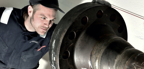
This method is used for the detection of surface and near-surface flaws in ferromagnetic materials and is primarily used for crack detection. The specimen is magnetised either locally or overall, and if the material is sound the magnetic flux is predominantly inside the material. If, however, there is a surface-breaking flaw, the magnetic field is distorted, causing local magnetic flux leakage around the flaw. This leakage flux is displayed by covering the surface with very fine iron particles applied either dry or suspended in a liquid. The particles accumulate at the regions of flux leakage, producing a build-up which can be seen visually even when the crack opening is very narrow. Thus, a crack is indicated as a line of iron powder particles on the surface.

Dye Penetrant Inspection is a simple, low-cost method of detecting surface-breaking flaws such as cracks, laps, porosity, etc in non-conductive materials, for example Stainless Steel, Inconel etc.

A phased array is a unique ultrasonic probe consisting of a group of transmitters or receivers, allowing for precise control of sound waves. When used as a transmitter, the timing of element activation creates interference that can shape and angle the beam. As a receiver, the time differences between pulse arrivals at each element provide information about the pulse source's location. Similar to how our ears work, phased arrays can pinpoint sound directions. Unlike traditional twin-crystal probes, phased arrays adjust signal phases for desired beam angles. However, their performance relies on the number, size, and spacing of elements, requiring specialised signal processing equipment. Phased arrays are widely used in radar, sonar, and medical applications but face challenges in NDT ultrasonics due to metal penetration and wave mode issues.

Ultrasonic testing utilises sound waves to detect corrosion within materials. This NDT technique utilises array transducers that pulse elements in a sequence called phasing.

Radiographic Testing (RT) is a non-destructive testing method of inspecting materials for hidden flaws by using the ability of short X-rays and gamma rays to penetrate various materials and can be carried out on our clients' sites (under a strictly controlled environment) or within our Radiography bays.

The vast majority of radiography concerns the testing and grading of welds on pressurised piping, pressure vessels, high-capacity storage containers, pipelines, and some structural welds. Other tested materials include welder’s test plates, machined parts, plate metal, or pipewall (locating anomalies due to corrosion or mechanical damage).

Sonomatic have the ability to carry out radiography in any of our seven purpose-built radiography compounds as well as on client premises, under a strictly controlled environment. We can offer both conventional radiography as well as Digital Radiography methods. One of the advantages of digital radiography is that it does not require the use of wet chemicals for processing, diminishing the need for chemical use and the associated hazards that come with that process. There is also a smaller amount of radiation required to produce a digital image than that required to produce a conventional film.

Small controlled area photography

SCARPro source projector is used for industrial non-destructive testing applications of gamma radiography with Selenium-75. SCARPro can be used as a category I or II exposure device. When used in SCAR mode (category I), the SCARPro allows radiography to be performed in congested work areas with a minimal distance to the controlled areas. When used as a traditional projector (category II), standard Sentinel™ source guide tubes and collimators allow the Selenium-75 source to be used for axial, radial and panoramic exposures.

X-ray systems: OVDX – OpenVision™

Live video x-ray system enables real time, qualitative screening for corrosion under insulation (CUI). CUI causes unscheduled downtime if not identified and corrected, posing major cost and safety issues. Identify problem areas quickly, saving valuable time and resources. Scan miles with OpenVision™ versus mere feet accomplished by other NDT methods. OVDX effectively increases inspection productivity in refinery, pipeline and offshore environments. Video images and still image captures can be stored using a DVR.

Detects temperature variations and has been widely used to detect breakdowns of thermal insulation of cryogenic storage vessels and thermal linings of furnaces etc. Areas of damaged and waterlogged insulation can be detected using this technique.

Thermography does not give a definitive indication of corrosion, but highlights areas where corrosion may develop in the future. The possibility of intermittent wetting and drying-out of insulation, especially on hot plant and pipework, leading to a misleading result needs to be kept in mind.

Long-Range Ultrasonic Testing (LRUT) is a method for the rapid screening of pipework for corrosion and erosion. The technique differs from conventional ultrasonic testing in that it uses plate or Lamb waves instead of bulk waves and the frequency is in the order of kHz rather than MHz. Plate waves penetrate the whole thickness of the plate and the ratio of plate thickness to the ultrasonic wavelength is such that the waves on the two surfaces interact.

We use MFL (magnetic flux leakage) to inspect the floor of the tanks,  operator maps out the floor of the tanks and inspects the area using specialised equipment. Results are instant.

The use of Short-Range Guided Wave Ultrasonics makes it possible to inspect hidden areas of concern that are normally unreachable using conventional Ultrasonics or alternative methods of inspection. Short Range Guided Wave inspection utilises bulk wave ultrasonics to effectively scan distances as far as 1 meter along components to screen for areas of material loss from corrosion and pitting.

Benefits

  • Effective screening tool for searching for material loss in hidden locations.
  • Highly productive Inspection.
  • Instant Results.
  • Highly portable equipment – equivalent to one UT set and probe.
  • Electronic data.
  • Minimal inspection team, (potential one person).
  • Rope Access deployable.
  • Applications.

Applications

  • Trunnion inspection – highly effective for locating and categorising corrosion within trunnions.
  • Pipe support inspection – Assessment of corrosion found at pipe supports (CUPS).
  • Deck penetrations – Capable of locating and assessing hidden corrosion at deck penetrations.
  • Vessel saddle inspection – Scan vessel shell for hidden material loss under the vessel saddle.
  • Deck plate inspection – Scan deck plates for areas of corrosion on far wall of plate.
  • Storage Tank Annular Ring inspection – Ideal for the inspection of tank annular rings where there is no internal access to tank floor to monitor for corrosion.
  • Soil to Air Interface – Detection of corrosion and material loss below ground level where pipe work penetrates ground.

Sonomatic is a leader in such techniques as TOFD and has designed and continues to develop innovative inspection methods that are applied by our own team of experienced field service engineers.

Time of Flight Diffraction (TOFD) can be used for multiple different applications, however, it is primarily used for rapid weld testing of circumferential and axial weld seams or perpendicular TOFD scanning. Sonomatic RAIS offers TOFD using the Olympus Omniscan inspection technology. TOFD offers rapid weld inspection with excellent flaw detection and sizing capacities. The diffraction technique provides critical sizing capability with relative indifference to bevel angle or flaw orientation. TOFD can be utilised on its own or in conjunction with other NDT techniques.

  • Based on diffraction, so relatively indifferent to weld bevel angles and flaw orientation.
  • Uses time of arrival of signals received from crack tips for accurate defect positioning and sizing.
  • Precise sizing capability makes it an ideal flaw monitoring method.
  • Quick to set up and perform an inspection, as a single beam offers a large area of coverage.
  • Rapid scanning with imaging and full data recording.
  • Can also be used for corrosion inspections.
  • Required equipment is more economical than phased array, due to conventional nature (single pulser and receiver). and use of conventional probes.
  • Highly sensitive to all weld flaw types.

Accreditations

Get in touch with us today